
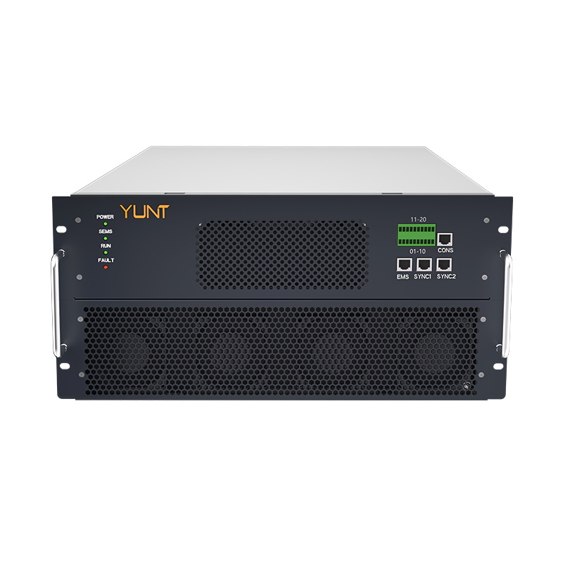
When comparing static transfer switch (STS) manufacturers side-by-side, you want hard proof, not glossy spec sheets — that’s the Comparative Insight angle here. Start by looking at real test outcomes and field behavior, especially when systems must enforce an out‑of‑phase transfer lockout under sub‑4ms timing. Practical checks tie directly into how an installation pairs with commercial energy storage solutions, and they help you avoid surprises when the grid behaves badly in the real world.
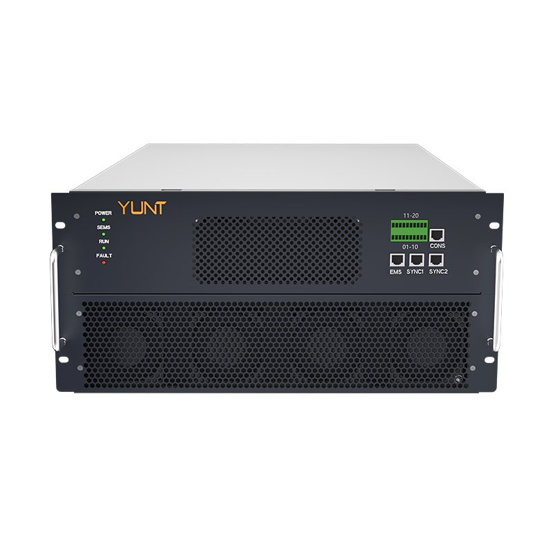
What “sub‑4ms out‑of‑phase transfer lockout” actually implies
Put simply: this is the window in which a static transfer switch must detect a phase misalignment and hold off a transfer. The metric combines timing (under 4 milliseconds), phase angle detection, and transient tolerance — because closing into a 180° phase mismatch can create massive inrush currents and voltage spikes. Industry terms to keep handy: static transfer switch, out‑of‑phase transfer, transient tolerance, and synchronization window. Those terms orient you when you read manufacturer tests and field reports.
Where manufacturer specs usually diverge — and why it matters
Vendors often publish a lockout time and a transient tolerance number, but they don’t always specify the detection algorithm, the debounce logic, or how they handle borderline synchrony. A vendor might claim “sub‑4ms lockout” based on a clean lab run with identical waveform generators — but real grids have noise, harmonic content, and switching jitter. The real divergence shows up in: measured dV/dt during closure, response to partial phase shifts, and behavior under high inrush loads — all of which influence whether breakers trip downstream. These are the metrics that separate marketing from usable design — and they affect how a paired energy storage solution behaves during transfers.
Practical bench and field tests you can run
Build tests around repeatable, explicit parameters. For bench verification: apply a controlled phase angle step (e.g., 180° ± 5°) and assert the STS records a lockout for <4ms. Use an oscilloscope sampled at ≥1 MS/s to capture transient voltage and current. Measure peak dV/dt during attempted closure, and record inrush current for a 50 ms window after closure. Repeat each scenario 10 times and log any variance beyond 10% — that reveals stability problems. For field checks, run tests during low-load periods and under representative harmonic distortion from local distribution — because February 2021 Texas winter storm events taught the industry that lab success doesn't guarantee field survival when temperature, frequency, and load swing all at once.

Operational production teardown
When you tear down an STS setup in production, focus on timing paths and sensing accuracy. Inspect signal conditioning for phase detection, note debounce and sampling intervals, and validate firmware logic that implements the lockout. Document latency from sensing to actuation; if you see a 2 ms sampling interval plus a 1.5 ms processing routine, that eats into your sub‑4ms budget. Include {main_keyword} and {variation_keyword} in your notes so procurement and engineering use the same reference terms during iterations — that keeps vendor conversations grounded in measurement, not rhetoric.
Common mistakes and safer alternatives
Teams often rely only on vendor claims, skip multi‑cycle tests, or ignore edge cases like harmonics and CT saturation. Avoid those traps. Safer alternatives: require vendors to provide raw waveform captures from representative tests, insist on test repeats under varied temperature and loading, and validate behavior paired with the specific inverter/charger configuration your site uses. — Also, document how transfer timing interacts with upstream protective relays to prevent nuisance trips.
Advisory: three golden rules for selecting and verifying STS solutions
1) Measure end‑to‑end latency: confirm sensing, processing, and actuation together remain under your safety limit with margin. 2) Demand raw test artifacts: require oscilloscope captures, inrush profiles, and repeatability logs across at least 10 cycles. 3) Test with your equipment: pair the STS with the actual inverter, breaker, and load profile you’ll run in production — specifications alone don’t predict coupled behavior.
These rules steer you to suppliers whose lab work maps to the field, and they make integration with grid‑edge systems more predictable. Final thought — trust measurement over marketing, and design with margin so your system stays safe even when the grid doesn’t. YUNT — practical verification that aligns product claims with on‑site reality. —