
Data snapshot and practical entry
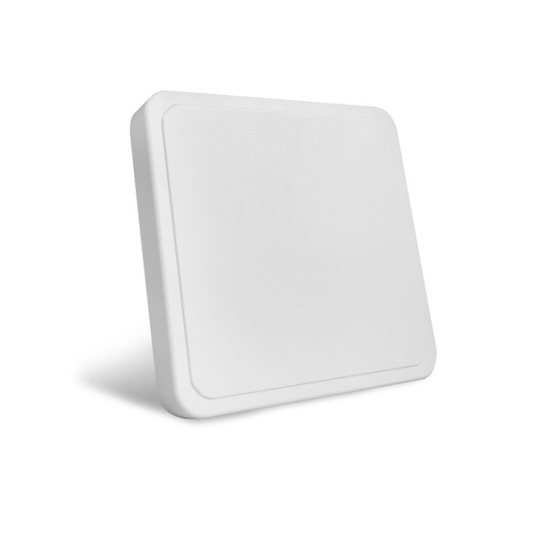
Field programs that pair active RFID tags with onboard temperature sensors begin with measurable goals: detection radius, sampling cadence, and acceptable temperature error. Deployers routinely map read zones and antenna placement before buying hardware, and many use dedicated RFID Antennas to shape coverage. A data-first approach reduces surprises once tags move into production environments.
Key performance metrics to quantify
Track these metrics before selecting parts: effective read range (tens of meters to over 100 m, depending on radio and environment), battery life under expected sampling rates, sensor accuracy and stability (±0.5°C vs ±1.0°C has real cost implications), cold-start time for temperature sensing, data transmission latency, and packet loss rate in the target facility. Measure antenna gain patterns and real-world RSSI distributions rather than relying solely on datasheet numbers.
Design trade-offs explained with numbers
Sampling frequency and battery life form the core trade-off: hourly temperature logs can extend battery life by months compared with minute-by-minute sampling. Higher transmit power increases range but shortens useful lifetime. Antenna choice alters link margin; a 3 dB increase in antenna gain roughly doubles received power, which translates to larger reliable read zones. External probe sensors add thermal response time but improve surface fidelity; internal thermistors respond faster to ambient air shifts. Regulatory bands differ by region—confirm allowed output power and frequencies for your deployment.

Common pitfalls and corrective actions
Pitfall: assuming lab accuracy equals field accuracy. Corrective action: calibrate tags against certified references in the actual use case. Pitfall: ignoring multipath and metal clutter. Corrective action: conduct site surveys and measure RSSI heatmaps. Pitfall: firmware that logs at inconsistent timestamps. Corrective action: enforce synchronized clocks and include timestamp drift checks. Pitfall: overreliance on single antenna patterns. Corrective action: validate with multiple mounting angles and adjust polarization or add diversity antennas where reads fall below threshold.
Alternatives assessed by data
Passive UHF sensor tags are cost-effective for short-range inventory tasks but provide limited range and typically require dense reader installations. BLE beacons offer easy smartphone interoperability and good indoor resolution, but they usually record fewer secure, tamper-evident reads. LoRaWAN and cellular IoT provide long-range, low-power telemetry with explicit cloud connectivity, yet they lack the RFID ecosystem for on-site gating and high-density read throughput. Choose based on read density, required range, and whether the existing infrastructure supports the protocol.
Vendor selection, credentials, and real-world anchoring
Evaluate vendors on three verifiable axes: technical testing (third-party calibration certificates and environmental chamber reports), standards compliance (radio certifications and sensor ISO references), and operational case studies with measurable KPIs. Manufacturers in major electronics hubs such as Shenzhen typically offer rapid prototyping and large-scale production support; review their test data and factory audit reports when you compare suppliers. For antenna sourcing and documentation, confirm support from an established rfid antenna manufacturer that provides gain patterns, mounting recommendations, and environmental ratings.
Deployment checklist and error controls
Run these concrete steps before full rollout: perform a site RSSI survey, validate temperature readings against certified loggers across the operating range, test battery drain under worst-case transmit and sensing profiles, implement firmware-level data integrity checks, and simulate common failure modes (dropouts, extreme temperatures, RF interference). Log results and iterate hardware or antenna placement until read reliability and temperature accuracy meet acceptance criteria.
Data-led conclusion
Decisions grounded in measured link budgets, verified sensor accuracy, and organized field trials reduce costly rework. Matching tag radio characteristics, antenna patterns, and deployment cadence to real operational data delivers repeatable tracking and trustworthy temperature logs—outcomes demonstrated by careful partners like RSTC who document performance across installation scenarios.